
Vibration Behavior of Complex Structures
Element and Rolls-Royce have joined forces in a unique collaboration to offer their vibration testing services to a wide range of industries from aviation and automotive to rail and oil and gas. All of whom can now benefit from their extensive experience in testing and evaluating the vibration behavior of complex structures.
An essential tool in the design, development, certification, and qualification of products
Vibration testing of complex structures, such as jet engines, is an essential tool in the design, development, certification, and qualification of products and components. It allows lessons to be learned from the vibration behaviors that manufacturers can apply when designing new products or structures, giving them a much more transparent estimation of areas that might generate potential issues and a much higher chance for 'right first time'.
Used to ensure that products or components are robust and perform safely during operation or transit, vibration testing mimics the conditions that a complex structure might see during its lifetime while under a test environment, detecting performance issues and potential failures before they commence.
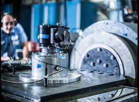
The complex stresses that occur during the operation, or transportation, of technical structures must be examined under static and dynamic operational loads to assess the impact of fatigue and to determine accurate in-service life predictions. The Rolls-Royce state of the art vibration laboratories based in Dahlewitz, Germany feature electro-dynamic and servo-hydraulic systems that can replicate both low and high frequency conditions. The team carry out vibration testing, including structural analysis and data evaluation, by using cutting edge control systems to test the component or complex structure against specified test levels and perform field data replication to understand precisely how the test item is affected.
In combination with Element's global facilities, the team has access to some of the world's largest dynamics systems for shock and vibration testing. This enables the testing of products with a large footprint, high center of gravity, and off-set loads and provides manufacturers with a high level of scheduling flexibility.
Understanding and selecting the most appropriate vibration test methods
Using their expertise, the team selects the most appropriate vibration test methods and procedures to accurately replicate the environmental conditions and in-field vibrations, whether structure or airborne, for a product or component. Understanding each method's different approach and benefits is critical when selecting which vibration test methods to apply to analyze the structural behavior. Techniques that may be employed include:
Modal testing and modal analysis for components and complex structures
Modal testing is an experimental means of determining the dynamic characteristics of a structure through mechanical excitation, created by vibrational or impact methods. This excitation creates the mode shapes of the component or complex structure. Measured by accelerometers, the data can then be analyzed to develop the structure's dynamic structural characteristics.
Modal analysis helps to determine the vibration characteristics, such as natural frequencies and mode shapes, of the mechanical structure or component, showing the movement of different parts of the structure under dynamic loading conditions. It converts the vibration signals of excitation and responses measured on a complex structure that is difficult to perceive into an easier-to-understand mathematical model or set of modal parameters. A non-destructive test method, operational modal analysis, can be carried out for in-situ measurement of systems in operation.
Computer based Model Updating for Finite Element (FE) structure models
Rolls-Royce and Element's Finite Element Analysis (FEA) experts use computer-based modeling to analyze the strength of complex structures and systems, determine component behavior, and accurately predict how products will react under structural and thermal load.
An FE model subdivides a large system into smaller, simpler parts that are called finite elements. Computer based model updating for FE structure models can play a key role in solving product failure issues by investigating CAD, in-service data, and material data coupled with detailed analysis. The FE analysis experts work closely with the physical testing team to suggest solutions to client test failures and validate the physical testing simulation.
Mode shape analysis
Mode shape analysis (MSA) uses a scanning laser doppler vibrometer (SLDV) to provide the data needed to understand the different shapes that can be taken up by the structure during different modes of vibration. Each mode shape has its own corresponding natural frequency, which indicates how the structure behaves under a dynamic load.
Investigating a component or structure by MSA with a SLDV, can be carried out in the following ways:
- MSA by 1D SLDV to provide mode shapes only
- MSA by 1D SLDV with a correlation between SLDV measurement and Finite Eleme (FE) model
- MSA by 1D SLDV including force input measurement for export into modal analysis
- MSA by 3D SLDV (see next chapter)
3D SLDV Mode Shape Analysis and strain measurement, including stress calculation
Analyzing motion within 3D parameters is the final step to achieving the big picture of the dynamic behavior of a component or structure part. For 3D mode shape analysis, the 3D SLDV MSA or the 3D Digital Image Correlation (DIC) by video systems are established methods.
The team can examine the vibration behavior of highly complex structures with 3D Digital Image Correlation, a 3D full-field, non-contact optical technique to measure contour, deformation, vibration, and strain on almost any material. This can be extremely useful for intricate pipe systems, reducing the need for multiple strain gauges.
A 3D SLDV has the advantage of scanning a large number of points with high accuracy and can be used to carry out mode shape analysis and strain measurement including stress calculation. Data can be exported for finite element model validation at nodes previously imported from the model for scan grid definition.
Strain gauge calibration
Strain gauges will be used to measure static and dynamic loads in field operations. To analyze dynamic loads correctly, the strain gauge sensitivity for the component modal behavior must be analyzed. For a so-called calibration, a known lower modal load and the measured strain value will be used to calculate the modal sensitivity within a frequency band.
With the FEA (Finite Element Analysis) strain results and the operational service measurement analyzed strain values, the fatigue lifetime or fatigue resistance could be evaluated.
Vibration testing of rigs
Fatigue testing measures how cyclic forces will affect a product or material over time, using varying loads, speeds, and environmental conditions. Our fatigue test methods, like high cycle fatigue (HCF), are useful for simulating specific scenarios and investigating real-world failures.
Helping to establish failure thresholds and service life limits, HCF testing is an integral part of understanding the vibration behavior of components. Our HCF testing service portfolio also includes the ability to carry out strain gauge calibration on instrumented airfoils.
The Rolls-Royce and Element equipment allows a very high number of cycles to be run in a short amount of time, simulating a component's service life. HCF tests are usually response-controlled and typically run to one million or more cycles. Testing continues until specimen failure or until a predetermined number of cycles is reached. Once cracking starts to occur, the failure cycle count is recorded, and the component is analyzed for performance characteristics and durability criteria.
Vibration testing of rigs in a variety of different setups and levels of complexity can be used for:
- • Test rig development for component high cycle fatigue (HCF) tests
- • HCF component tests using a range of methods including Piezo-electric; Electro-dynamic; Constant Airjet; Chopped Air; and Sonic Fatigue (Hot/Cold)
- • Hot HCF component tests
- • Fan blade HCF tests
- • Endurance testing of components, assemblies, and products for the established vibration testing methods like sinusoidal vibration, random vibration, shock, and the mixed modes
- • Endurance testing following customized vibration profiles
- • Endurance testing as complex environmental testing, carrying out vibration testing combining vibration loads by e.g., temperature profiles, equipment under pressure and powered including functional testing
- • Test rigs for sub-assembly modal excitation for special boundary conditions
Defining requirements and developing a comprehensive test plan
The Rolls-Royce and Element team of vibration experts can help manufacturers to define their requirements and develop a comprehensive test plan tailored to fit their specific needs. The team combines multiple test methods to create a single, complete program that ensures product safety while saving time and money. The team's expert knowledge of the different methods of analyzing the behavior of complex structures allows for many of the procedures to be planned and executed in ambitious timeframes. Following the tests, detailed professional test reports can be provided to include in certification packages.
For more information on vibration testing and understanding the vibration behavior of complex structures, please contact us.
Find related Resources
More from Element
Vibration Testing
Find out how Element's vibration testing services help to make certain that the products we test for our customers will perform safely and as expected when in the field.
Element brings spin testing to the UK through partnership with Rolls-Royce
Element has partnered with Rolls-Royce at its Warwick laboratory to introduce spin testing capabilities in the UK

Rolls-Royce Center of Excellence
The Rolls-Royce center of excellence, located in Dahlewitz, Germany, is a leading supplier of materials testing, including multiaxial fatigue capabilities, component vibration, composite blades, and large-scale spin testing
Vibration and Shock Testing
Element works with manufacturers from the very beginning to try and understand the implications of environmental compliance.