
Test to Success & ASTM F3211 Fatigue to Fracture Methodologies

By Engaged Expert
Maciej JakuckiMaciej Jakucki has performed and managed a wide variety of medical testing projects and programs to meet FDA and CE requirements.
Testing to success or testing to failure using Fatigue to Fracture (FtF) - does one method provide more insights into cardiovascular device performance than the other?
Industries such as Aerospace and Transportation predominantly test fatigue under a range of conditions so that they can predict fatigue life behavior based on design characteristics and material properties. In the medical industry, fatigue life analysis through fatigue to fracture hasn’t been used quite as often. The material properties of the common medical materials are established, but it is becoming more frequently used alongside the test to success method to characterize design performance.
The standard methodology for fatigue to fracture testing, ASTM F3211, was developed in response to the increase in utilizing FtF testing to help model failure methods and limits for cardiovascular implants. Prior to its release, a standard method for cardiovascular device testing was not readily available.
In this article, we review the test to success and fatigue to fracture methodologies, their differences, and how they are critical in evaluating the durability of stents, heart valves, occluders, and other cardiovascular devices for safety and regulatory approval.
Test to success methodology
Historically, fatigue resistance for cardiovascular devices has been evaluated by the “test to success” strategy. This means most cardiac and intravascular implants are subjected to 400 or 600 million cycles of durability testing without any observations of fracture in order to mimic a service life of 10 or 15 years, respectively. Devices such as vena cava filters, which undergo respiratory loading, are tested to 100 million cycles and superficial femoral artery (SFA) devices, subject to gait motion loading, are typically tested to 10 million cycles to simulate 10 years of service life.
If a device is loaded to physiologically-relevant conditions that mimic the expected service life without failure, the test is considered successful. Testing to success essentially provides a minimum verification of the performance of the device.
Using the Bayes Success Run Theorem, 29 to 59 non-fractured samples are required for 90% or 95% reliability and 95% confidence level. To raise reliability to 99%, 299 defect-free samples would be required, which is a deterrent with both time and investment. Device manufacturers make the reliability target determination based on device risk and regulatory guidance, but it is most common to see sample sizes of 29 test specimens for these configurations. Abbreviated studies sometimes will contain 6, 12, or 15 samples.
Testing to success typically tries to employ boundary conditions both for load/strain and device configurations (e.g., overlapping stents, corrosion potential). A successful test does not result in any fractures, thereby preventing manufacturers from gaining insights about the device’s failure modes and characterizing the fatigue behavior. While benchmark performance data is helpful, it does not address concerns about worst-case hyper physiological events, but rather minimum performance with an assumed, built-in safety factor.
If you’d like to learn more about testing to success, our articles on Pulsatile Durability Testing of Complex Intravascular Devices and Cardiovascular Implant Pulsatile Fatigue Testing Calculations outline ways to utilize this method. Additionally, ASTM F2477, Standard Test Methods for in vitro Pulsatile Durability Testing of Vascular Stents, is a common method in the cardiovascular industry that implements the test to success approach.
Fatigue to Fracture (FtF) methodology
Fatigue is a progressive weakening or cumulative occurrence of localized permanent deformation due to cyclic loading. Fatigue to Fracture (FtF) testing provides data about a material or device’s failure modes and fatigue behavior, which is critical information for preventing adverse conditions like radial support loss, thrombus formation, or perforation of the vessels. FtF testing applies controlled loads or strains at a variety of levels above those used for test to success evaluation. These hyper-physiological tests are intended to predict the device’s fatigue life by causing fracture. Observing fracture progression and location improves understanding of the structural impact caused by different types of fractures.
Before FtF testing, Finite Element Analysis (FEA) can be used to determine the type of test sample (whole device vs. component or test coupon), worst-case and failure test conditions, and several other performance characteristics. While these computational models evaluate the stresses and strains on the tested systems, the models need to be validated with experimental data to ensure the predicted results align with benchtop results. Mechanical properties are imported into the models and then fatigue to fracture testing yields defined failure points for model comparison. Two key guidance documents for FEA simulation are ASTM F2514, Standard Guide for Finite Element Analysis (FEA) of Metallic Vascular Stents Subjected to Uniform Radial Loading, and ASME V&V40.
Since the goal of FtF is understanding how and when a device failure occurs, the failure criteria need to be established prior to the start of the test. A single fracture may not necessarily result in loss of device function, in which case a conditional probability analysis should be performed as fracture probabilities may evolve while device failure progresses. Acceptable (if any) and unacceptable fractures should be defined, and failure may be defined as permanent deformation or fracture that renders the device harmful or ineffective.
ASTM F3211 guide for fatigue to fracture
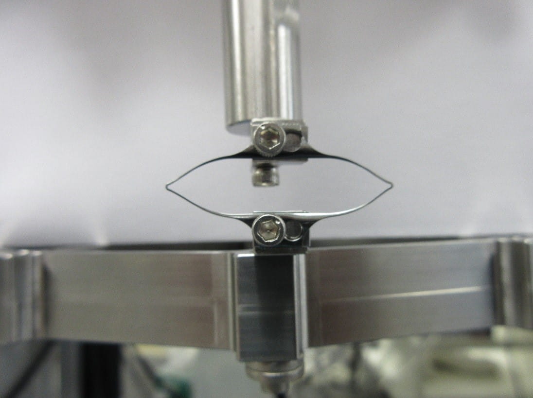
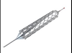
ASTM F3211, Standard Guide for Fatigue-to-Fracture (FtF) Methodology for Cardiovascular Medical Devices, outlines the FtF scope, test procedure and data reporting to build a mathematical fatigue life model. The model characterizes the device or coupon behavior over a variety of loads and cycles. Test modes are then identified based on expected in vivo loading conditions (e.g., torsion, bending, tension, compression), and test specimens are selected from finished devices or components so that they represent worst-case scenarios. Figure 1 shows an example of diamond-shaped fatigue to fracture test specimens. Coupons or specimens should be tested in the final condition including any post-processing, sterilization, etc. to identically represent the end product.
Risk analysis tools and literature review help determine the physiological loads and durability requirements, including acceptance and failure criteria. The standard recommends performing device preconditioning to simulate deployment and defines test monitoring of load/displacement. Additional steps in the methodology pertain to test protocol development, including test frequency, sample size, test duration, etc. and test instrument verification.
Finally, a device inspection strategy should be developed. Inspections may be performed at predetermined intervals or continuously through the use of high speed video with strobe lighting or electrical conductivity measurements. Inspections may also be performed by removing the specimens from the testers and analyzing with scanning electron microscopy (SEM) or high-resolution computed tomography (micro-CT). However, care should be taken to not compromise the samples during removal and installation.
Load step up or down?
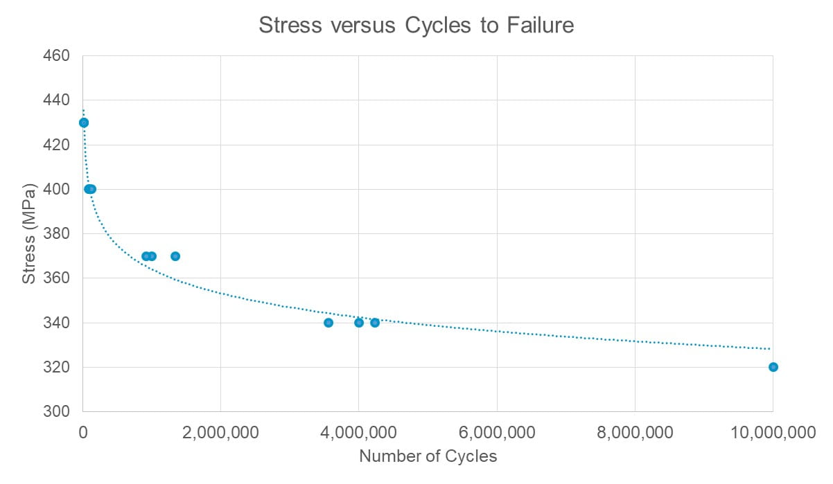
Testing is performed at multiple load levels (amplitude and/or mean) until the test specimens reach a pre-determined number of cycles, known as the stress or strain fatigue limit. Statistically, samples tested below this value are more likely to survive, whereas samples tested above the limit are likely to fail at a lower cycle count. Consideration should be given to the physiological responses of the upper and lower bounds of the load selections, ensuring that they are not above or below what would be physiologically relevant.
The basic step up-step down technique allows a user to estimate a load based on the fatigue strength for a determined number of cycles. Depending on the results, the user then increases (steps up) or decreases (steps down) the load to get to the next data point. The size of steps will determine the accuracy of the model. If limited prior data is available, it can be time-efficient to start with high load levels to get fractures quickly and predict fatigue performance based on the resultant equations. Additional testing is then performed with more samples at lower load levels to build the fatigue life data (Figure 2).
The results from the testing outlined above help determine the fatigue safety factor (FSF) to apply to the device and validate the computational models with part performance. If the model information doesn’t align, adjustments can be made to improve the predictability and use the data for future devices.
Customized S-N testing example
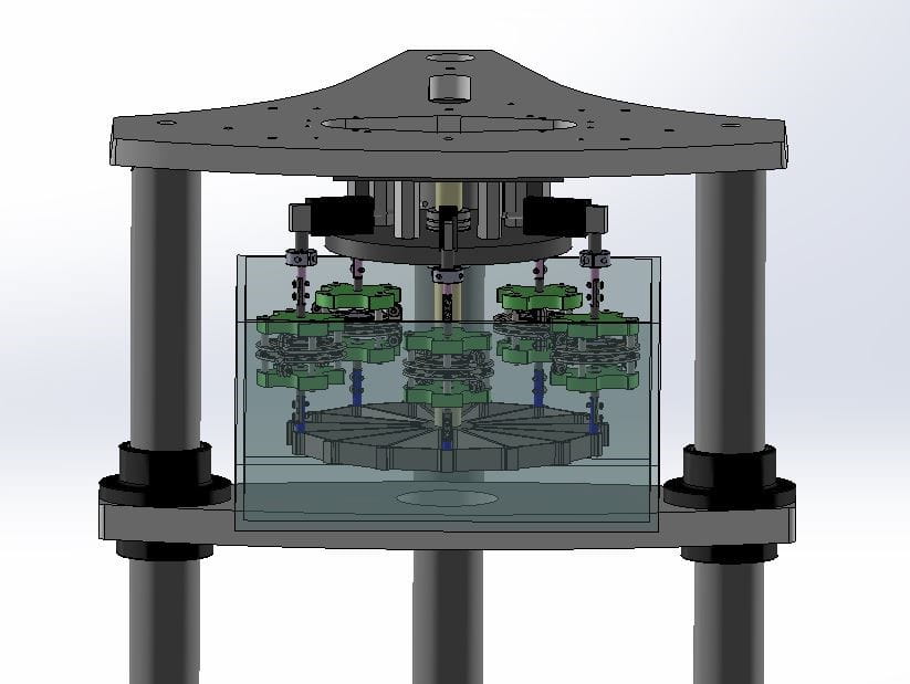
In an axial fatigue S-N testing example, customized coupons were loaded with different levels of displacement amplitudes at 20 Hz. Samples were mounted on a multi-specimen spider fixture on a 3230 ElectroForce Test Instrument (Figure 3 shows a similar setup). Each sample or station had its own load cell for recording peak-valley data throughout testing.
The axial fatigue test began with the highest displacement/strain and a 10 million cycle target runout. Peak-valley load data vs. number of cycles, mean, and alternating displacements were recorded for each of the samples. Test results showed fracture locations at the apex, links or shoulders of the test coupons.
Summary
Both test to success and ASTM F3211 fatigue to fracture tests are important for characterization of cardiovascular medical devices. While test to success tests focus on completing 400 or 600 million of cycles without failures to show physiological confidence, FtF seeks to characterize the fatigue and fracture behavior of implants by loading them at hyper-physiological levels. When fractures occur, the resultant data can be used to evaluate the material and design behavior of the device, providing critical insight into the potential physiological impact, or allowing for adjustments to be made to the design geometries.
The methodologies outlined above are intended to provide structural fatigue assessment data for cardiovascular medical devices. When combined with statistical analyses, the methods become a powerful tool for designing and evaluating devices that are safe and effective for the patients.
Element has one of the most expansive cardiovascular medical device testing scopes in the world, ranging from axial, torsional, bending, and pulsatile durability testing, to nickel ion leaching, corrosion, and particulate analysis. Contact us to discuss how we can help with your test project.
Find related Resources
Related Services

Pulsatile Durability Testing of Complex Intravascular Devices
Designed to demonstrate the long-term integrity of devices under mechanical fatigue, pulsatile durability typically simulates ten years of post-implantation use under accelerated conditions.

Stroboscope Visual Inspection of Medical Devices
Digital stroboscopes facilitate visual inspections of cardiovascular medical devices as they undergo accelerated fatigue. The strobe light is a very useful tool in detecting device failures and tracking motion during testing.
Preconditioning Stents for Fatigue through Simulated Use Testing
Simulated use testing of implantable cardiovascular medical devices is a well-established non-clinical engineering test used to serve many purposes including delivery, deployment and retraction of a stent.
Stent & Graft Testing
Element’s cardiovascular device experts offer a comprehensive suite of stent and graft testing including pulsatile durability, fatigue, visual inspection, and custom test methods.